
Method for Protecting Biological Objects from the Negative Influence of Technogenic Electromagnetic Radiation
Abstract
The method for protecting biological objects from the negative influence of technogenic electromagnetic (EM) radiation in a wide range of frequencies, which consists of creating around a biological object (BO) or between it and the source of technogenic EM radiation a special EM field in the form of a fractal coherent matrix, using a fractal-matrix coherent transformer to create the field. A coherent transformer is a self-affine lattice (resonator) formed from ringed topological lines, which create a slit-like raster, and is a universal Fourier transformer that harmonizes the amplitude, phase, frequency and polarization vector of external technogenic radiation and the BO's own EM radiation. The shape of the resonator's field is a spatial holographic matrix whose multi-level gradation is a set of annular raster lattices that are symmetric with at least the three orthogonal basis vectors X, Y, Z with a subsequent release to multidimensionality and with the formation of a spatial monostructural form with an infinite number of inherent derivative components.
The transformation of external radiation, both technogenic and the BO's inherent radiation, occurs in accordance with the direct and inverse Fourier transform with the formation of a coherent matrix of EM wave superpositions. As a result of the process of resonant harmonization in a coherent environment of external radiations that differ in nature, the transformation of technogenic EM radiation to a form that does not conflict with the BO is achieved. Moreover, the transformation does not affect the functioning of the technical devices generating the EM radiation.

The coherent transformer can be placed on the BO, next to it, on the source of technogenic EM radiation, or between the BO and the source.
Description
Methods for protecting biological objects from technogenic EM radiation in a wide range of frequencies and can be used in the everyday life of each person to protect against the negative influence of surrounding technogenic radiation, including 5G mobile communication systems (3.5-28 GHz).
Before proceeding to the description of the invention, it should be noted that all methods for protecting a BO from technogenic EM radiation come down to reducing the intensity of the EM pulse, reducing the exposure time, or increasing the distance from the BO to the radiation source, which leads to inconvenience or the inability to properly use the source of EM radiation, especially when using it to transmit large amounts of information.
The task for which the claimed method is intended is to protect a biological object, in particular the human body, from the negative influence of technogenic EM radiation of a wide range of frequencies without reducing the effectiveness of the sources generating it and without imposing additional requirements on them.
In this aspect, it is most rational to change the structure of the EM pulse arising from the radiation source, transforming it into a form safe for the BO, without losing its effectiveness.
The restructuring of technogenic EM radiation in the proposed method implies changing its amplitude-frequency spectrum from an arbitrary form to a coherent form through the influence of a coherent field created by a transformer that initiates the process of counter- harmonization of amplitudes, phases, frequencies, polarization vectors, and the EM radiation incident on it.
This process, which is implemented using a coherent transformer (resonator), is proven and protected (Russian Federation Patent No. 2231137, No. 2217181, No. 2284062, No. 2308065, No. 2312384, EU patents No. 005535515-0002, No. 005535515-0001, No. 005535515-0003, No. 005535515-0004) and is later described in more detail.
The claimed method is based on self-affine holographic objects' ability to transform the EM pulses interacting with them according to their characteristics.
Holography (from ancient Greek: ὅλος – whole, γράφω – I writing) It is based on two physical phenomena — diffraction and interference of EM waves. The physical idea is that under the imposition of several wave pulses, under certain conditions, an interference pattern occurs, that is, a spatial regular system of maxima and minima of the intensity of electromagnetic radiation in the form of a stationary field having a fractal self-affine structure.
According to contemporary scientific concepts, when interacting with external EM
In order for this interference pattern to be stable for the time necessary to observe, and in order for it to be recorded, these EM pulses must be harmonized spatially and temporally across frequencies and amplitudes. Such EM waves are called coherent.
Based on the principle of superposition, if EM waves coincide in phase, then they add with each other and produce a resultant wave with an amplitude equal to the sum of their amplitudes. If they meet in antiphase, then they cancel each other out. If two opposite EM pulses are identical in phase, amplitude, frequency, and polarization vectors, then their amplitudes are multiplied.
The resulting interaction of two coherent waves is a fractal standing wave. That is, the interference pattern will be stable in time (phase), in amplitude (power), polarization vector (direction), and frequency (stability). Since any fractal construct is a self-affine structure, that is, formed from its own analogues, this property underlies the production and restoration of holograms in its individual fragments.
To obtain a holographic response, the resonator must either itself have the ability to transform the radiation incident on it into a coherent form, or the incident radiation must initially be coherent. The hologram arising from the resonator carries not only the same characteristics and properties as the radiation incident on the resonator, but also the specific features of the resonator topology itself. As a result, if the resonator initiates a coherent transformation of incoherent EM radiation incident on it, the resulting hologram has the same ability to transform an EM pulse of the corresponding frequency range that interacts with it into a coherent state.
The strength and intensity of the coherent field fall in proportion to the square of the distance from the resonator. Thus, the given EM field can transform EM radiation interacting with it into a coherent form, if its strength and intensity is not lower than the strength and intensity of the opposite radiation. Such interaction is possible due to the fractality of the resonator, not only when the frequencies coincide, but also when they are similar at multiple scales.
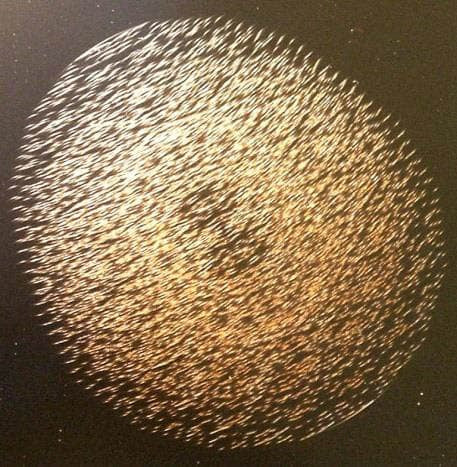
Below is an image of a self-affine lattice fixed on a solid medium (left), and a photograph of the holographic response resulting from the incoherent EM radiation's interaction with the slit topological surface of the lattice (right).

It is known that coherence (cohaerens – in communication) is the harmonized flow in time and in space of several oscillatory processes.
The term "coherence" means the absence of conflicts, consistency, and communication. When applied to EM radiation, it refers to consistency and communication between EM oscillations and waves. Oscillations are called fully coherent if the difference of their phases at the observation point remains constant in time. Oscillations (waves) are called partially coherent if the difference of their phases changes very slowly, and incoherent if the phase difference changes randomly.
Thus, "coherence" means consistency and communication between EM oscillations. Energy losses at a point of coherent radiation are minimized.
An example of obtaining coherent radiation using a novel approach is creating regular structures on the surface of solids. These structures then act as resonators.

Of interest is the case where it would be possible to generate EM oscillations on not a single frequency, but a wide range of frequencies, while preserving interrelationships between them such that they remain coherent, not only in time, but also in space, like a laser.
So-called self-affine structures generated in the form of annular slits open unexpected possibilities for use in scientific research and technology. A self-affine fractal is defined as a structure that is invariant after simultaneous yet quantitatively different changes in the scale along different spatial axes.


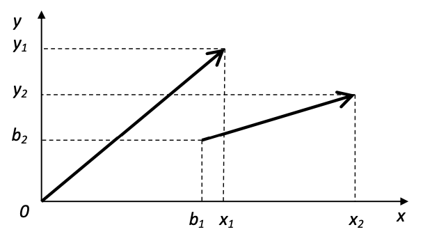
Affine transformations can also define a rotation by angle a about the origin. After performing transformations representing the multiplication of points of the figure by the scale factor m1= 2i and rotations by an angle proportional to the coefficient m2= 2j, and overlaying the original drawing, we obtain the self-affine structure shown below.


Modeling
During the modeling, a stationary model and two-dimensional and three-dimensional non-stationary models were analyzed.
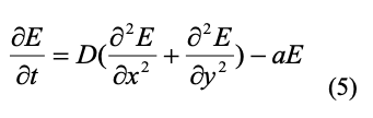
For the stationary case, the interaction of EM radiation waves with the wafer's surface was modeled using a mathematical model incorporating wave number k, dielectric constant ε, cyclic frequency ω, speed of light c, radius vector r, polar angle, and electric component E.


During calculations on a computer, the radiation's periodic behavior was changed relative to the size of the wafer, when the wavelength of the incident radiation and the periodic behavior of the resonator's surface pattern were compared, taking into account its dimensions.
The obtained modeling results show that the strength of the electric field, after interacting with the self-affine fractal lattice, is redistributed so that the graphs of the field distribution over the surface become regular, a trait that remains almost unchanged when changing the frequency of the incident radiation over a wide range.


Modeling result for incident radiation with a frequency of 2 periods per 1 rotation by the angle. Amplitude is on the left; phase is on the right.

Periodic behavior of incident radiation of 64 periods per 1 rotation by angle. Amplitude is on the left; phase is on the right.
Non-stationary model: The fractal served as the foundation for building the mathematical model. The rings on the surface are grooves about 1.3 microns deep and 1 μm wide. The minimum distance between the "grooves" is 1 μm. The wafer's outer diameter was 6 mm. When interacting with the conductor, an electric field causes charges to shift and increases the concentration of charges in the "grooves" relative to adjacent areas.

The main result of the modeling is that regardless of the conditions at the boundary, the steady-state solution is stable and soliton-like. Its shape does not change with changing boundary conditions. This means that the resonator's self-affine surface transforms radiation in such a way that the result of this process does not depend on the characteristics of the radiation incident on it.


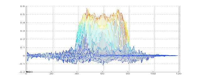
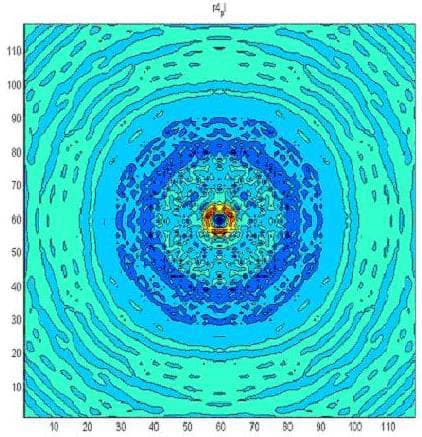
Distribution of the amplitude's spectral power density on the wafer's surface through time t>test. Amplitude is on the left; phase is on the right.

The figure clearly shows a luminous "scaly" dome (hologram), similar to the results of a computational experiment.
A three-dimensional model was also considered, which differs from the two-dimensional model by the presence of a third spatial coordinate z. This makes it possible to create a more complete representation of the interaction of the self-affine topological surface with radiation, and obtain the spatial distribution of strength E. The resonator's surface lies in plane x0y with the origin at the center of the resonator. The z-axis is orthogonal to this plane.


Electric field strength on the surface of the resonator (lower graph, z= 0) and so on in layers above the surface: 0.1mm; 0.2mm; 0.3mm; 0.4mm; 0.5mm. When z>0.2mm, the wave decays.
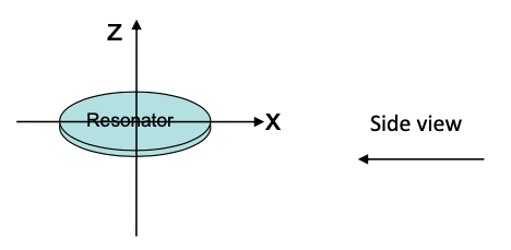

Electric field strength for the steady state, when using a resonator with a double-sided design, side view.
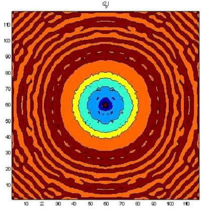
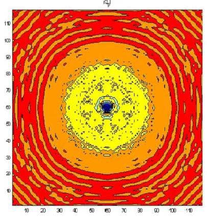


The next figure presents the results of modeling using a three-dimensional non-stationary model. The red color corresponds to the maximum field strength, while violet corresponds to the minimum.


Distribution of field strength E above the resonator from 0.28 to 14.18 (V/m) with incident radiation at 2.4 GHz.

Distribution of field intensity I over the resonator from 0.08 to 201.05 (W/m2) with incident radiation at 2.4 GHz.
Thus, the self-affine surface topography transforms the radiation incident on it into a coherent form, even for a wide range of frequencies.
- It was shown that a coherent transformer, when excited by EM radiation, forms a stationary, multi-frequency coherent wave (hologram) in space, which is stable and soliton-like regardless of the boundary conditions. Its shape does not change with changing boundary conditions. This means that the result of this transformation does not depend on the characteristics of the radiation incident on it.
- Our experiments have demonstrated that a semiconducting wafer with a self-affine topography on its surface transforms a broad spectrum of incident radiation into a coherent form. It redistributes the incident radiation in terms of its wavelength as well as its phase, in accordance with its topography. Its use opens up fundamentally new opportunities for creating a variety of devices:
– coherent transformers that harmonize the interaction of several wave fronts;
– broadband resonators with distribution of energy through a space that is self-similar and carries information about the amplitude, wavelength, and phase of incident radiation. - This development will find application in the form of a protective device that transforms external radiation, including 5G communication systems (3.5-28 GHz), into a form that is harmonized with the inherent radiation of an organism's cells, thus making it safe for a biological object.
Based on the fact that biological objects are open physical systems that have an EM nature and function under conditions of constant exchange of energy and matter with the environment, they have a specific design for fixing the set of the molecular structural lattice's nodal centers, which are interconnected in a unified spatial matrix. Since the molecular structural lattice reflects a specific model of the fundamental interrelationships of the object, it is possible to consider the biological organization as an organization that initiates a constant EM superposition. This superposition is able to react by means of its own resonance to any particular external impulse, causing changes in the molecular structure that gave rise to it, making it possible to have a targeted effect on the biological object.
As a result of the counter-harmonization of technogenic radiation interacting with the BO's own electromagnetic radiation, which is a superposition of cellular metabolism processes, the coherent transformer used in this method initiates optimization of the organism's adaptive physiological characteristics, thereby making the interaction conflict-free, which is proven by experimental data.
The essence of the claimed method is as follows.
The method for protecting biological objects from the negative influence of technogenic EM radiation in a wide range of frequencies, which includes creating around a biological object (BO) or between it and the source of technogenic EM radiation a special EM field in the form of a fractal coherent matrix (hologram), using a fractal-matrix coherent transformer to create the field.
The coherent transformer used is a self-affine lattice (resonator), formed from circular topological lines, creating a slit-like raster.
The resonator's structural lattice is a Fourier transformer that harmonizes the amplitudes, phases, frequencies and polarization vectors of external technogenic radiation and the BO's inherent EM radiation. The coherent field that forms around the resonator resonates with the surrounding EM waves., including with the inherent radiation of the human body's biological cells, transforming it into a consistent form, and makes the interaction conflict-free.
The resonator's coherently transforming impulse forms a spatial matrix whose multilevel gradation is a set of annular raster lattices symmetric with at least the three orthogonal basis vectors X, Y, Z with a subsequent release to multidimensionality N and with the formation of a spatial monostructural form with an infinite number of inherent components satisfying Noether's theorem, which requires the formation of the maximum spatial symmetry of the object's field structure, and the condition of interaction in the form of a self-affine hypersphere.
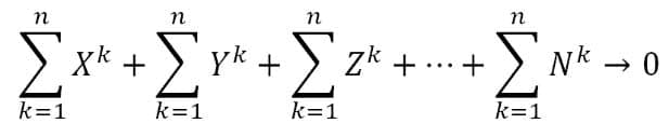
where X, Y, Z, N are the fractalization vectors of the system of a annular self-affine circuit, k = 1..n is the number of circuit elements.
According to the Noether theorem, each continuous symmetry of a physical system corresponds to a certain law of conservation. In our case, the symmetry of the diffraction grating, formed from annular topological lines, unambiguously forms a coherent EM field, which is a hologram as a stable wave structure. This is confirmed by the principle of holograms (D. Gabor – Yu.N. Denisyuk), according to which any wave superposition carries the same properties as the regular structure that generated it.
During the proposed exposure to a coherently transformed EM field, the complex of the wave characteristics of the inherent radiation of the cells of a biological object is brought into a resonant state that is determined by strict fractal-matrix schematization, which causes the system to respond. Such counter-harmonization of the wave characteristics, by eliminating conflict, leads to the stabilization of all metabolic processes and, as a result, an increase in the BO's adaptive abilities under conditions of exposure to technogenic EM radiation.
The wave characteristics and stabilization of the metabolic processes of the BO are harmonized by exposing it to an EM field coherently transformed by the resonator's self-affine annular grating. For the resonator's self-affine annular grating, we used the fractal-planar projection of a special spatial structural-holographic construction, fixed on a solid medium and formed from annular topological slit-like lines that create a raster (RF Patent No. 2231137, No. 2217181, No. 2284062, No. 2308065, No. 2312384; EU Patent No. 005535515-0002, No. 005535515-0001, No. 005535515-0003, No. 005535515-0004).


The coherently transforming resonator can be made in various embodiments, depending on its location, and be directly on the BO (attached to clothing, hung from a cord, etc.), near the BO (for example, in the same room), attached to the source of technogenic EM radiation (mobile phone, computer, home appliances, etc.) or be between the BO and the radiation source.
The proposed method for protecting biological objects from technogenic EM radiation contributes to a reduction (elimination) of the negative influence of technogenic EM radiation on the BO, especially with the spread of 5G communication systems. This method makes it possible to protect a biological object from the negative influence of broadband EM radiation.
The claimed method has no analogues and can be used in the daily life of a person that exists among a large number of electronic devices emitting an EM field.
Bibliography
- Kopyltsov A.V., Serov I.N., Lukyanov G.N. Interaction of a Semiconducting Wafer with a Self-Affine Surface Topography with Electromagnetic Radiation. Nanotechnology. – 2006. – No. 4(8). – pp. 44-49.
- Serov I.N., Lukyanov G.N., Kopyltsov A.V. Mathematical Modeling of the Interaction of Electromagnetic Radiation with a Silicon Self-Affine Surface. ENGECON Bulletin, "Technical Sciences" series – 2007 Issue 6(19) – pp. 199-205.
- Serov I.N., Sysoyev V.N., Rybina L.A., Ananeva V.N., Effect of products with a nano- scale fractal topology on several vital processes and human ecology, Nanotechnology, 2006, April, No. 1, pp. 146-151
- Serov I.N., V.N. Sysoyev., Evaluation of the effectiveness of using Aires Shield electromagnetic anomaly neutralizers to reduce the negative influence of the electromagnetic field caused by the operation of a cellular phone, International Journal of Applied and Fundamental Research. – 2014. – No. 8 – pp. 81-85
- Slabko V.V., Principles of Holography, Soros Educational Journal, No. 7, 1997
- D. Gabor. "Holography (1948-1971)". Nobel Lecture, Advances in the Physical Sciences, Vol. 109, Issue 1, January 1973
- Yu. N. Denisyuk. Principles of Holography. — Leningrad: Publishing House of the State Optical Institute, 1979.
- A.S. Mitrofanov. Principles of amplification of optical radiation. Teaching aid. Saint Petersburg. Saint Petersburg State University of Information Technologies, Mechanics, and Optics, 2005
- Potapov A.A., Fractals in Radiophysics and Radiolocation: Topology of the Sample. Edition 2, revised and added to. – Moscow: Universitetskaya Kniga, 2005.
- Mandelbrot, V.V., Self-affine fractals and fractal dimension, Physica Scripta 32 (1985) 257–260.